

Marine Pollution (Prevention of Pollution from Ships) Act, 1986 (Act No. 2 of 1986)ScheduleInternational Convention for the Prevention of Pollution from Ships, 1973Protocol of 1978Relating to the International Convention for the Prevention of Pollution from Ships, 1973Annexes : RegulationsAnnex I : Regulations for the Prevention of Pollution by OilChapter II : Requirements for Control of Operational PollutionRegulation 13F : Prevention of Oil Pollution in event of Collision or Stranding |
| (1) | This Regulation shall apply to oil tankers of 600 tons deadweight and above— |
| (a) | for which the building contract is placed on or after 6 July 1993; |
| (b) | in the absence of a building contract, the keels of which are laid or which are at a similar stage of construction on or after 6 January 1994; |
| (c) | the delivery of which is on or after 6 July 1996; or |
| (d) | which have undergone a major conversion- |
| (i) | for which the contract is placed after 6 July 1993; |
| (ii) | in the absence of a contract, the construction work of which is begun after 6 January 1994; or |
| (iii) | which is completed after 6 July 1996. |
(2) Every oil tanker of 5 000 tons deadweight and above shall:
| (a) | in lieu of Regulation 13E, as applicable, comply with the requirements of paragraph (3) unless it is subject to the provisions of paragraphs (4) and (5); and |
| (b) | comply, if applicable, with the requirements of paragraph (6). |
| (3) | The entire cargo tank length shall be protected by ballast tanks or spaces other than cargo or fuel oil tanks as follows: |
(a) Wing tanks or spaces
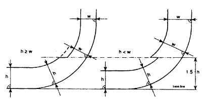
Wing tanks or spaces shall extend either for the full depth of the ship's side or from the top of the double bottom to the uppermost deck, disregarding a rounded gunwale where fitted. They shall be arranged such that the cargo tanks are located inboard of the moulded line of the side shell plating, nowhere less than the distance w which, as shown in figure 1, is measured at any cross-section at right angles to the side shell, as specified below:
| w = | 0.5 + DW/20 000 (m); or |
| w = | 2.0 m, whichever is the lesser. The minimum value of w = 1.0 m. |
| (b) | Double bottom tanks or spaces |
At any cross-section the depth of each double bottom tank or space shall be such that the distance h between the bottom of the cargo tanks and the moulded line of the bottom shell plating measured at right angles to the bottom shell plating as shown in figure 1 is not less than specified below:
h = B/15 (m); or
h = 2.0 m, whichever is the lesser. The minimum value of h = 1.0 m.
| (c) | Turn of the bilge area or at locations without a clearly defined turn of the bilge |
When the distances h and w are different, the distance w shall have preference at levels exceeding 1.5h above the baseline as shown in figure 1.
(d) The aggregate capacity of ballast tanks
On crude oil tankers of 20 000 tons deadweight and above and product carriers of 30 000 tons deadweight and above, the aggregate capacity of wing tanks, double bottom tanks, forepeak tanks and afterpeak tanks shall not be less than the capacity of segregated ballast tanks necessary to meet the requirements of Regulation 13. Wing tanks or spaces and double bottom tanks used to meet the requirements of Regulation 13 shall be located as uniformly as practicable along the cargo tank length. Additional segregated ballast capacity provided for reducing longitudinal hull girder bending stress, trim, etc., may be located anywhere within the ship.
(e) Suction wells in cargo tanks
Suction wells in cargo tanks may protrude into the double bottom below the boundary line defined by the distance h provided that such wells are as small as practicable and the distance between the well bottom and bottom shell plating is not less than 0.5h.
(f) Ballast and cargo piping
Ballast piping and other piping such as sounding and vent piping to ballast tanks shall not pass through cargo tanks. Cargo piping and similar piping to cargo tanks shall not pass through ballast tanks. Exemptions to this requirement may be granted for short lengths of piping, provided that they are completely welded or equivalent thereto.

Figure 1 - Cargo tank boundary lines for the purpose of paragraph (3)
(4)
| (a) | Double bottom tanks or spaces as required by paragraph (3)(b) may be dispensed with, provided that the design of the tanker is such that the cargo and vapour pressure exerted on the bottom shell plating forming a single boundary between the cargo and the sea does not exceed the external hydrostatic water pressure, as expressed by the following formula: |
![]()
where:
| hc = | height of cargo in contact with the bottom shell plating in metres |
| pc = | maximum cargo density in t/m3 |
| dn = | minimum operating draught under any expected loading condition in metres |
| ps = | density of sea water in t/m3 |
| Δp = | maximum set pressure of pressure/vacuum valve provided for the cargo tank in bars |
| f = | safety factor = 1.1 |
| g = | standard acceleration of gravity (9.81 m/s2). |
| (b) | Any horizontal partition necessary to fulfill the above requirements shall be located at a height of not less that B/6 or 6 metres, whichever is the lesser, but not more than 0.6D, above the baseline where D is the moulded depth amidships. |
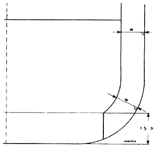
| (c) | The location of wing tanks or spaces shall be as defined in paragraph (3)(a) except that, below a level 1.5h above the baseline where h is as defined in paragraph (3)(b), the cargo tank boundary line may be vertical down to the bottom plating, as shown in figure 2. |

Figure 2 - Cargo tank boundary lines for the purpose of paragraph (4)
| (5) | Other methods of design and construction of oil tankers may also be accepted as alternatives to the requirements prescribed in paragraph (3), provided that such methods ensure at least the same level of protection against oil pollution in the event of collision or stranding and are approved in principle by the Marine guidelines developed by the Organization. |
| (6) | For oil tankers of 20 000 tons deadweight and above the damage assumptions prescr5ibed in Regulation 25(2)(b) shall be supplemented by the following assumed bottom raking damage: |
| (a) | longitudinal extent: |
| (i) | ships of 75 000 tons deadweight and above: 0.6L measured from the forward perpendicular; |
| (ii) | ships of less than 75 000 tons deadweight: 0.4L measured from the forward perpendicular; |
| (b) | transverse extent: B/3 anywhere in the bottom; |
| (c) | vertical extent: breach of the outer hull. |
| (7) | Oil tankers of less than 5 000 tons deadweight shall: |
| (a) | at least be fitted with double bottom tanks or spaces having such a depth that the distance h specified in paragraph (3)(b) complies with the following: |
| h = | B/15 (m) |
with a minimum value of h = 0.76 m;
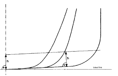
in the turn of the bilge area and at locations without a clearly defined turn of the bilge, the cargo tank boundary line shall run parallel to the line of the mid-ship flat bottom as shown in figure 3; and
| (b) | be provided with cargo tanks so arranged that the capacity of each cargo tank does not exceed 700 m3 unless wing tanks or spaces are arranged in accordance with paragraph (3)(a) complying with the following: |
w = 0.4 + 2.4 DW/20 000 (m)
with a minimum value of w = 0.76 m.

Figure 3 - Cargo tank boundary lines for the purpose of paragraph (7)
| (8) | Oil shall not be carried in any space extending forward of a collision bulkhead located in accordance with Regulation II-1/11 of the International Convention for the Safety of Life at Sea, 1974, as amended. An oil tanker that is not required to have a collision bulkhead in accordance with that Regulation shall not carry oil in any space extending forward of the transverse plane perpendicular to the centreline that is located as if it were a collision bulkhead located in accordance with that Regulation. |
| (9) | In approving the design and construction of oil tankers to be built in accordance with the provisions of this Regulation, Administrations shall have due regard to the general safety aspects including the need for the maintenance and inspection of wing and double bottom tanks or spaces. |