

Occupational Health and Safety Act, 1993 (Act No. 85 of 1993)RegulationsExplosives Regulations, 2024Radio Frequency Device Guidelines5. Assessment of RF Devices |
| 5.1 | Flow Chart |
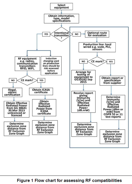
The flow chart in Figure 1 below provides guidance for determining the exclusion zones (distances) for intentional and unintentional RF emitting devices.

| 5.2 | ICASA certificate example |
An example of an ICASA certificate is shown in the Figure 2 below

| 5.3 | Exclusion Distance Graph |
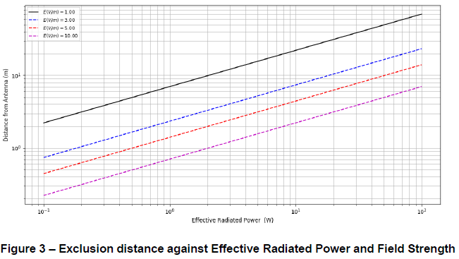
The exclusion distance graph to be used in conjunction with the flow chart in Figure 1 is shown in Figure 3 below against frequency for different field strengths: 1; 3; 5; 10 V/m.

Following the description below and the formulas 1 to 4, additional field strengths and distances not indicated in the graph in Figure 3 above can be calculated. These are first order calculations that do not account for resonances, reflections, diffraction, or absorption associated with radio waves.
The method for generating the distance map is based on the combination of the following equations. The power density equation is shown in (1) below:
(1)
![]()
S= Power Density
P = Power output/ power input to antenna (in Watts)
G = gain
R =Distance (in meters)
The E-field- power density S relationship for uniform plane waves in free space is shown in (2). Power density S is in W/m2.
Equation (2) makes use of the approximate impedance of free space medium, which is 377 Ω.
(2)
![]()
Equations (1) and (2) are combined to form equation (3). Equation (3) allows the calculation of R, the distance from a point source antenna in metres with gain G and Effective transmitted power P in Watts. R is calculated for a specified E-field strength in volts per meter.
(3)

The effective power P can account for gain differences for different antenna types and account for uncertainties such as transmitter power variation using equation (4). In (4). UdB is the uncertainty correction factor, PTX is the transmitted power in Watts, and GdBd is the maximum antenna gain in any direction. An example on how to use (4) is given in 6.1.
(4)
![]()
The effective radiated power in Watt is then calculated as:
(5)

| Where: | E is the field strength from the graph in volts per metre. |
R is the test distance from the source in metres.